I am trying to change the center of rotation for parts in a step so that the visible part will pivot about itself and not the center of the entire project. I have been able to do this in some steps, but don’t know how I did it. I think it has something to do with the triad, local/world and custom selectors but can’t figure out the proper steps. Appreciate any help.
1 Like
In case it’s not clear, I want the visible parts in a step to rotate about the center of the visible part(s) while in the viewer.
Hi @user6388 , by default an items triad is location at its local 0,0,0 coordinates which is determined by how its originally drawn in the CAD system. If you want to rotate it around another point, you can do so by first selecting the object then using the traid placement mode P to position the roation point.
see this video blog at around 2.30 for more information…
how to have it so that when a part is on either side of the screen it can be rotated whilst remaining stationary? Like how it is by default in the middle of the screen
Hi @user18553 ,
Im not sure I follow, could you send a screenshot to illustrate, or message me a link to your project in the designer to look at?
If you want to roate a part whilst not translating, simply rotating it (press alt key to change to rotation instead of translate) should do it?
Thanks Support
I have watched those videos many times. I can change the axis of rotation while in designer, using the triad, but while in the viewer or even in the designer it revolves about the project not the part. In the project linked below the parts visible in steps 7,8 and 10 will revolve about their visible axis, or at least close, but step 11 revolves about the project center. I am not able to figure out how I made steps 7,8 and 10 work.
1 Like
Are you meaning how the transition looks when you go from step 10-11 and how to camera rotates?
If you are just changing the camera it has nothing to do with the traid/origin of the parts. When you go between steps and the camera moves, the parts stay still, think of it like a camera man walking and moving a camera into position. And he will always take the shortest route.
Since the assembly you are focused on in step 11 is off to the side/offset then the camera naturally has to swing round to move from position A (Step 10) to position B (step 11).
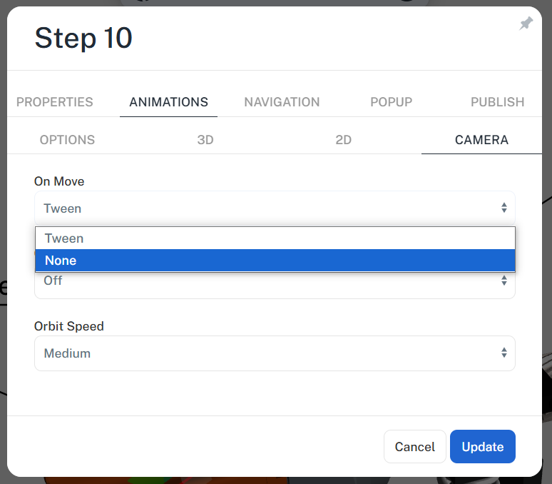
If you didnt like the animation, you could switch off the camera animation for that step…
or perhaps use step transitions to hide it
or put in a intermediary play step, between 10 and 11 so the camera animates different (e.g. instead of just A-B its going A-B-C)
No, I am refering to the ability to rotate an object in Cadasio both in the designer and especially in the viewer. I want the object that is visible in step 11 to rotate around its axis by using the middle mouse button (wheel) and dragging the mouse to rotate the object, as it is being rotated in steps 7,8 and 10.
1 Like
If you are wanting the ability for the viewer to be able to rotate parts the same way in the designer, e.g. with the triad, if im honest im not sure that would be something we would be adding anytime soon - we certainly have not had any other requests.
If you want the camera to rotate around the object on the screen…at the moment we dont have a way to manually place the centre of rotation for the camera…however if you double click an object, it not only fits it to the screen, but it does reset the centre of ratotation for the camera, which may help you (youd have to do this on your step then update the step)?
I believe that is what I’m looking for. I’ll check it out.